CE-3 Restoration Part 2 : The Physical Hurdles
- Mar 31
- 1 min read

In the Part 1 of this restoration series, I outlined the diagnostic process for my vintage Boss CE-3 Chorus. This pedal had been pulled from my board due to random noise bursts, but its sonic character is irreplaceable. Today, the parts have arrived, and we move from theory to execution.
The restoration plan is threefold:
Trimmer Replacement: Swap out the corroded component causing the instability.
Electrolytic Recapping: Replace all capacitors, utilizing high-grade audio capacitors for the signal path to improve fidelity.
ACA to PSA Conversion: Modify the power section to accept modern 9V standards.

I began by removing the jacks and knobs to free the PCB from the chassis, ensuring a stable workspace.

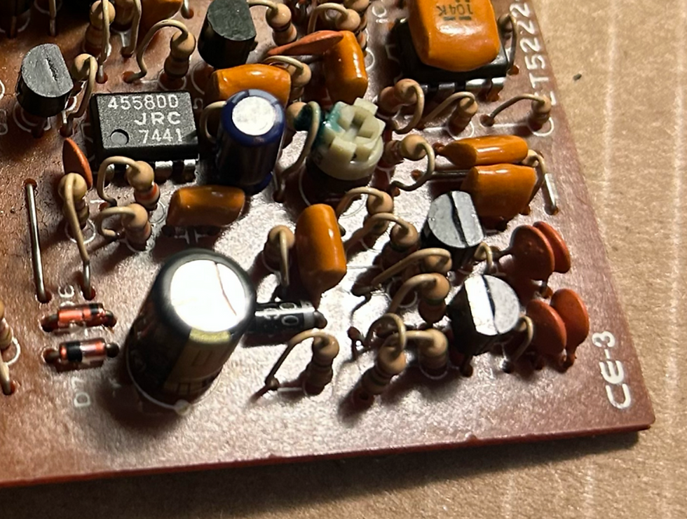
The first step is the capacitor exchange. I removed them one by one, strictly verifying values and polarity. On these components, the white stripe indicates the negative side. You’ll notice a brown substance at the base of the capacitors in the photo. This isn’t leakage; it’s factory glue used for mechanical stability. To prevent board damage, I carefully scored this glue with a blade before desoldering.

The removal was clean. Boss PCBs from this era are user-friendly; note the white dot printed on the board clearly marking the negative pole.

Here are the replacements. I double-checked the capacitance and voltage ratings before inserting the leads and soldering.

Once soldered, the excess leads were trimmed flush with a pair of nippers.
The first unit is installed. I proceeded to replace the remaining capacitors using this method. Full article on Patreon @yewplaysmusic